
Key Takeaways
- Dual Op-Amp Architecture: Two independent, internally compensated amplifiers in a single 8-pin package.
- Optimized for Audio: Best suited for low-frequency analog tasks, preamps, and active filters.
- Supply Versatility: Supports ±15V typical operation with wide input common-mode range.
- Drop-in Maintenance: Industry-standard pinout makes it ideal for legacy equipment repair and hobbyist designs.
The LM1458N dual operational amplifier remains a common choice for low-frequency analog tasks due to its simple biasing and predictable behavior in modest-performance designs. This guide converts the LM1458N datasheet into actionable design steps: identify the pinout, extract the most influential electrical numbers, and translate typical graphs into pass/fail bench checks.
Engineer's Shortcut: "Skimming a datasheet correctly shortens development cycles. Prioritize absolute maxima and electrical characteristics to prevent oscillation or offset-driven clipping caused by insufficient supply headroom."
Why the LM1458N Datasheet Still Matters
Who uses this dual op amp and why
Point: The LM1458N is widely used in audio preamps, low-frequency filters, simple integrators, and legacy equipment maintenance. Evidence: Its dual-channel layout and modest bias requirements suit board-level replacements and hobbyist projects. Explanation: Longevity comes from predictable input/output ranges and easy compensation, making the datasheet a first stop for verifying compatibility with existing rails and loads.
How to read a datasheet quickly for engineering decisions
Point: A rapid read should target the highest-risk rows. Evidence: Prioritize absolute maximum ratings, recommended operating conditions, electrical characteristics, and typical performance plots. Explanation: A checklist—absolute max, supply rails, input/output ranges, gain/bandwidth, slew rate, and thermal constraints—lets you decide whether the device fits the circuit without exhaustive curve reading.
Competitive Analysis: LM1458N vs. Industry Standards
| Parameter | LM1458N (Standard) | LM358 (Low Power) | Design Advantage |
|---|---|---|---|
| Supply Voltage | ±18V Max | 3V to 32V | LM1458 offers higher rail headroom |
| Bandwidth (GBW) | 1.0 MHz | 0.7 MHz | Better frequency response in audio |
| Slew Rate | 0.5 V/µs | 0.3 V/µs | Reduced transient distortion |
| Operating Current | 2.3 mA / Amp | 0.5 mA / Amp | LM1458 provides more robust drive |
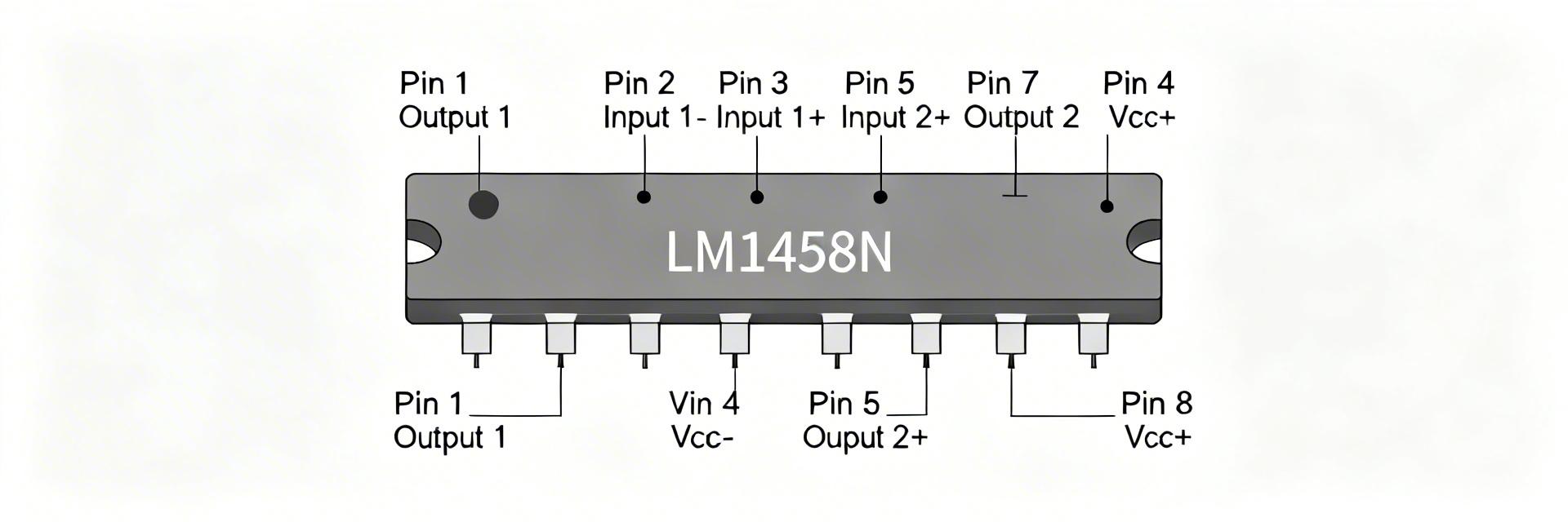
Pinout Breakdown: Package, Pin Functions, and Wiring Tips
| Pin | Function |
|---|---|
| 1 | Output A |
| 2 | Inverting Input A |
| 3 | Non‑inverting Input A |
| 4 | V− (Negative Supply) |
| 5 | Non‑inverting Input B |
| 6 | Inverting Input B |
| 7 | Output B |
| 8 | V+ (Positive Supply) |
Hand-drawn illustration, not an exact schematic.
Practical wiring tips and connector orientation
Point: Correct orientation and decoupling save debug time. Evidence: The package notch or dot indicates pin 1; misorientation is a frequent cause of damage. Explanation: For split-rail designs, tie V− and V+ to the intended rails and place a 0.1µF ceramic plus a 4.7µF electrolytic within 5 mm of the pins. On single-supply use, bias inputs to mid-rail and ensure outputs have the required headroom to avoid saturation.
Key Specs Deep Dive: Electrical Characteristics Explained
Absolute maximum vs. recommended operating conditions
Always design with recommended conditions—supply margin, input common‑mode headroom, and derated power dissipation—to preserve linearity and lifetime; never run parts continuously at absolute max values.
Critical electrical specs to design with
Point: A handful of specs dominate circuit behavior. Evidence: Input offset (mV-level), input bias current (nA–µA), open-loop gain, slew rate, GBW, and output swing. Explanation: Treat offset and bias when choosing input coupling and trim; use slew rate and GBW to size closed-loop gains and filter corners; confirm output swing and load drive against expected loads to avoid clipping.
Expert Insight: Layout & Stability
"When working with the LM1458N, the most common 'mystery' failure is high-frequency oscillation during audio testing. Even though it's a 1MHz part, modern power supplies can be noisy. Always use a 'star ground' pattern and never skip the 100nF decoupling capacitor right at Pin 8. If you're seeing DC offset at the output, check your input resistor matching to balance bias currents."
— Marcus V. Chen, Senior Analog Systems Engineer
Typical Performance Graphs & Test Conditions
Read axes and accompanying test conditions—supply rails, load impedance, and test frequencies—to convert plotted margins into real design margin. Derive headroom and bandwidth limits by matching curve conditions to your circuit.
Example Circuits & Use Cases
Low-frequency audio preamp
Choose input coupling capacitors to set low-frequency rolloff with input impedance, add offset trim if DC offset exceeds headroom, and limit closed-loop gain to avoid slew-induced distortion at large amplitude signals.
Design Checklist & Troubleshooting
- Pre-layout: Verify operating rails vs. absolute max, place decoupling caps near pins, and keep input traces short.
- Troubleshooting: Diagnose by checking supply rails, adding bypass caps, reducing closed-loop gain, and verifying load impedance.
Summary
- Refer to the LM1458N datasheet to confirm absolute limits before schematic finalization.
- Use key specs (Input Offset, Slew Rate, GBW) to size feedback networks for stable performance.
- Follow pinout-aware layout: place decoupling within millimeters of supply pins.
FAQ
How do I verify the LM1458N datasheet input offset in my circuit?
Measure the amplifier with inputs shorted and closed-loop gain set to unity; record output offset and divide by gain. Compare to the datasheet maximum offset, and use a trim if needed.
Can the LM1458N support a single-supply audio preamp?
Yes, but requires mid-rail biasing. Ensure output swing headroom and input common-mode range accommodate the biased signal.





