
The LMC6484AIN datasheet calls out ultra-low input bias currents into the femtoamp range, input offset voltages under 1 mV, and single-supply operation from 3 V to 15 V — key specs that make the quad rail-to-rail amplifier suitable for precision, low-power front ends. This article unpacks the datasheet, highlights make-or-break parameters, and shows how to reproduce test data in the lab.
Overview: What the LMC6484AIN Is (Background)
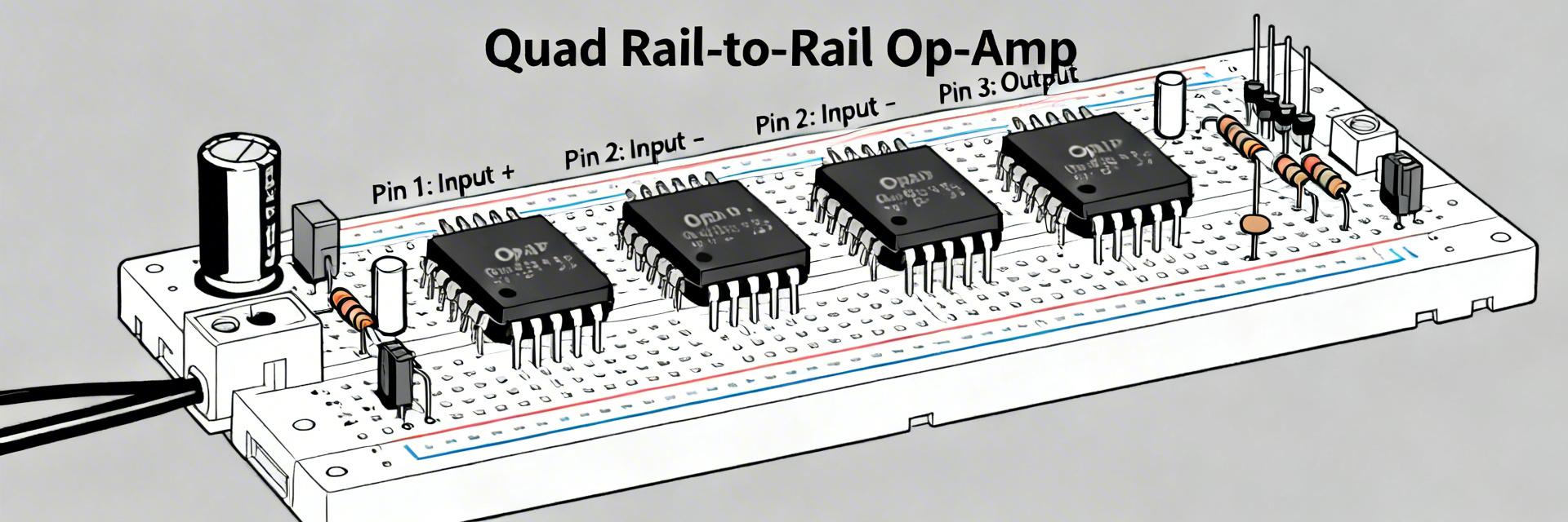
Device Summary & Intended Use
Point: The device is a quad CMOS operational amplifier with rail-to-rail inputs and outputs intended for single-supply precision tasks.
Evidence: The datasheet describes a four-channel op amp optimized for low bias and low supply current.
Explanation: You’ll typically see this in sensor front-ends, low-power buffering, and mixed-signal interfaces where input leakage and offset dominate error budgets.
At-a-Glance Key Specs
Guaranteed Max
Ultra-low leakage
- Input common-mode: Rail-to-rail extension
- Output swing: Within tens of mV of rails
- Supply current: Low µA per amplifier
- GBW: Modest (Low-frequency precision)
Explanation: When deciding rapidly, prioritize input bias, offset, and output swing — these three key specs usually determine suitability for precision single-supply designs.
Electrical Characteristics Deep Dive
| Parameter Category | Key Metrics | Impact on Design |
|---|---|---|
| DC Specifications | Offset Voltage, Input Bias, CMRR, PSRR | Sets baseline error; offset adds directly to measurement error. |
| AC Specifications | GBW, Slew Rate, Phase Margin, Noise | Determines dynamic behavior and signal chain settling time. |
DC Specs: Offset, Input Bias, CMRR, PSRR
Point: DC parameters set the baseline error for precision measurements.
Evidence: The datasheet provides typical and guaranteed values with explicit test conditions.
Explanation: Offset and bias set systematic and dependent errors — bias current interacting with source resistance creates voltage error; verify datasheet test conditions when comparing to your circuit.
AC Specs: Bandwidth, Slew Rate, Stability and Noise
Point: AC specs determine dynamic behavior and closed-loop performance.
Evidence: Gain-bandwidth product, small-signal bandwidth, slew rate, and input-referred noise are tabulated.
Explanation: Lower GBW and modest slew rate limit closed-loop gain; input-referred noise informs filter choices for low-frequency sensor chains.
Behavior Across Supplies & Temperature
Performance vs Supply Voltage (3 V to 15 V)
Point: Key parameters vary with supply voltage.
Evidence: Output swing, common-mode range, and slew performance change across recommended supply points.
Explanation: Expect reduced headroom near 3 V, slightly better swing and slew at higher voltages; confirm minimum supply for guaranteed specs before lock-in.
Temperature Effects & Operating Limits
Point: Temperature shifts affect offset, bias, and GBW.
Evidence: Offset drift and bias-current vs temperature curves are provided in datasheet figures.
Explanation: Plan thermal margins — budget offset drift into the system error budget and expect bias to rise at extremes; follow recommended operating range.
Reproducing Datasheet Test Data: Lab Methods & Pitfalls
Recommended Test Setups
Accurate reproduction requires mirroring datasheet conditions ($V_{CC}$, temp, source impedance). Use star grounding, local decoupling, and guarded inputs for bias tests. Bandwidth-limited measurements are essential for offset accuracy.
Common Measurement Pitfalls
Discrepancies often stem from PCB leakage, probe capacitance, or improper ground returns. Use high-quality guarding for femtoamp tests, short ground leads, and isolate probe capacitance to ensure reproducibility of published results.
Application Examples & Design Tips
Precision Sensor Front-End
Benefitting from low bias and R-to-R I/O. Choose feedback resistor values to limit noise and add RC filtering to match ADC bandwidth.
Rail-to-Rail Driver
When driving capacitive loads, use small series isolation resistors (snubbers) and keep loads light to maintain maximum swing.
Design Checklist & Selection Criteria
Quick Pre-Selection Checklist
- Supply range within 3V – 15V?
- Input common-mode covers rails?
- Bias/Offset limits meet error budget?
- Bandwidth/Slew sufficient for signal?
- Thermal specs match environment?
When to Choose the LMC6484AIN
Choose this part when bias and offset dominate your error budget. Opt for higher-speed or lower-noise amplifiers only when dynamic performance or very low broadband noise is the critical system bottleneck.
Summary
- The datasheet highlights ultra-low input bias, sub-1 mV offset typical, and rail-to-rail I/O across 3–15 V — these key specs make the part attractive for precision low-power front ends.
- Reproduce published results by matching datasheet test conditions: clean supplies, defined loads, guarded measurements, and documented bandwidth limits.
- Design choices: use series isolation for capacitive loads, plan for offset drift, and confirm operating margin at supply and temperature extremes.





