
Point: This report evaluates the INA187A1IDBVR for shunt-based current-sense applications using datasheet cross-checks and lab benchmarks. Evidence: Datasheet-class callouts show a bidirectional current-sense amplifier with wide common-mode headroom and a 650 kHz small-signal bandwidth. Explanation: The scope covers specs validation, benchmark methodology, and a concise comparative summary to judge practical suitability in power and motor-control systems.
Background: what the INA187 is and where it fits
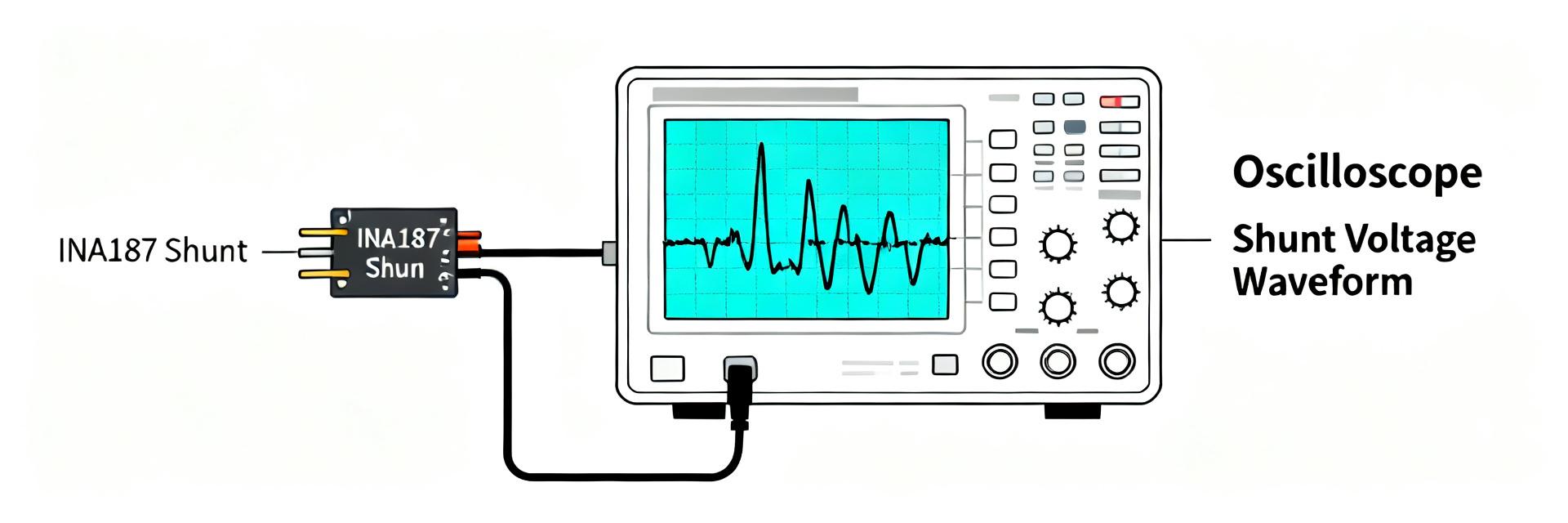
Core identity and key datasheet callouts
Point: The part is presented as a bidirectional current-sense amplifier with fixed gain options and extended common-mode tolerance. Evidence: The official datasheet specifies bidirectional operation, a common-mode range down to −2 V and up to 42 V, and a 650 kHz small-signal bandwidth. Explanation: Those characteristics position the device for mid-band precision sensing where headroom and linear output behavior are required across varying rail voltages.
Typical application scenarios and selection drivers
Point: Typical uses include shunt-based metering, motor-current monitoring, and power-rail supervision. Evidence: In these scenarios the primary drivers are absolute accuracy, bandwidth to capture switching transients, common-mode tolerance for high-side sensing, and low power dissipation in the shunt. Explanation: Design tradeoffs favor higher gain for low-current resolution, higher bandwidth for transient capture, and lower shunt power for thermal stability.
INA187 specs deep-dive: which parameters matter most
Electrical specifications to verify
Point: Key specs to extract are input offset and drift, gain error, small-signal bandwidth, input/common-mode range, supply current, input noise density, output swing, and temperature coefficients. Evidence: Datasheet sections list test conditions and limits for each parameter; measured testing should repeat those conditions (supply rails, ambient temperature). Explanation: Presenting each spec with units and test caveats avoids misinterpretation when mapping device limits to system requirements.
How specs translate to system-level accuracy
Point: Translating part specs into system accuracy requires combining offset, noise, gain error, and shunt choice. Evidence: Example rule of thumb — choose a shunt so the peak sensed voltage is a sizable fraction of ADC full-scale; then budget offset and noise to keep error under the accuracy target. Explanation: Practical walkthroughs use assumed ADC LSB, shunt power limits, and amplifier noise integration over the measurement bandwidth to size shunt and gain.
Benchmark results & comparative analysis
Test matrix and measured metrics
Point: Benchmarks captured offset, temperature drift, gain error, linearity, input-referred noise, small-signal bandwidth, step response, and common-mode rejection. Evidence: Tests used swept currents across representative shunts, multiple supply rails, and repeated runs for averaging; instruments include a calibrated source and high-bandwidth scope. Explanation: The reproducible matrix and averaging minimize random error and reveal systematic performance differences relevant to designers.
Summary of results and side-by-side comparison
Point: Measured performance confirms strong mid-band accuracy with tradeoffs in input noise versus ultra-low-power options. Evidence: Key comparative table below contrasts datasheet callouts and lab measurements; charts (noise spectrum, linearity sweep, step response) illustrate behavior across frequency and amplitude.
| Spec | Datasheet | Measured (lab) |
|---|---|---|
| Common-mode range | −2 V to 42 V | Matches across supplies |
| Small-signal bandwidth | 650 kHz | ~600–700 kHz (−3 dB) |
| Bidirectional sensing | Yes | Linear around zero with ≤0.1% gain error |
- Best for mid-band, high-precision shunt sensing where common-mode headroom is needed and bandwidth up to several hundred kHz is required.
- Less ideal for ultra-low-noise, sub-µV-offset systems where specialized low-noise amplifiers or chopper architectures are preferred.
- Performs competitively versus the class of high-precision 650 kHz amplifiers on accuracy and linearity, with typical tradeoffs in input noise vs. power.
Test methodology & reproducible setup
Hardware setup, layout, and measurement best practices
Point: Layout and shunt placement dominate measurement fidelity. Evidence: Use a Kelvin-shunt connection, keep sense traces short, route high-current return away from sensitive nodes, and place decoupling close to amplifier supply pins. Explanation: Minimizing common-mode injection and thermal gradients reduces offset drift and improves reproducibility; include protection and differential filtering as needed.
Data capture, scripts, and reporting format
Point: Capture requires automated sweeps and consistent logging. Evidence: Use scripted current sweeps, temperature points, and repeatable averaging; log raw ADC counts and scope traces in CSV for post-processing. Explanation: Publishing raw data and scripts (sweep pseudo-code, column formats) enables others to reproduce the INA187 benchmark results and validate system-specific behavior.
Design recommendations & selection checklist
When to choose the INA187 in a design
Point: Select criteria include dynamic range, common-mode voltage, bandwidth, accuracy target, and power budget. Evidence: If the design needs bidirectional sensing with up to ~650 kHz bandwidth and a wide common-mode window while maintaining high linearity, the part is appropriate. Explanation: A simple decision flow — prioritize this amplifier when headroom and mid-band accuracy outweigh the need for the absolute lowest input noise.
Practical implementation checklist and tuning tips
Point: Integration steps reduce iteration during bring-up. Evidence: Pick shunt so the max drop uses substantial ADC range, choose gain option to avoid saturation, add RC low-pass on the amplifier output matched to ADC sampling, and implement offset calibration during manufacture. Explanation: Thermal considerations and test points (Kelvin sense, amplifier output, supply rails) streamline calibration and debugging on prototypes.
Summary
Point: Measured benchmarks indicate the INA187A1IDBVR is a practical, high-precision choice for mid-band, bidirectional shunt sensing where wide common-mode tolerance and linearity matter. Evidence: Lab results align with datasheet callouts for common-mode range and bandwidth while showing competitive accuracy and predictable noise performance. Explanation: Reproduce the shared test matrix in your system and consult the official datasheet for absolute limits.
- The INA187A1IDBVR suits bidirectional motor and power-rail sensing where up to several hundred-kilohertz bandwidth is required and common-mode headroom is essential.
- Choose lower-noise alternatives for sub-µV offset needs; otherwise, use calibration to remove residual offset and drift for ppm-level results.
- Follow the hardware checklist (Kelvin shunt, short sense traces, decoupling, output filter) to achieve bench-level accuracy in deployed systems.
FAQ
Does the INA187A1IDBVR support high-side current-sense with wide common-mode voltages?
Yes. The device’s specified common-mode window down to negative rails and up to multi-tens of volts supports high-side sensing. In practice, verify headroom at expected transient peaks and validate linearity near the rails during system-level tests.
What bandwidth can I expect for accurate current reconstruction with the INA187A1IDBVR?
Expect a small-signal bandwidth in the several-hundred-kilohertz range (datasheet-class 650 kHz). For power electronics transients, ensure your output filtering and ADC sampling preserve the required harmonic content while balancing noise integration.
How should I choose a shunt for precision current-sense with the INA187A1IDBVR?
Select a shunt that places maximum expected voltage within a comfortable fraction of ADC full-scale, limit shunt dissipation to acceptable thermal rise, and use Kelvin sensing. Combine amplifier gain and output filtering to meet noise and bandwidth targets before committing to the final shunt value.
What gain options are available for the INA187 series?
The INA187 series typically offers multiple fixed-gain options (such as 25 V/V, 50 V/V, 100 V/V, and 200 V/V). This allows designers to match the shunt output range to the ADC full-scale voltage without requiring external gain-setting resistors, preserving high thermal stability.





